Selection & Case Study
Selection Case: Building an Indoor ROS 2 Navigation Robot with MS200 and MentorPi T1
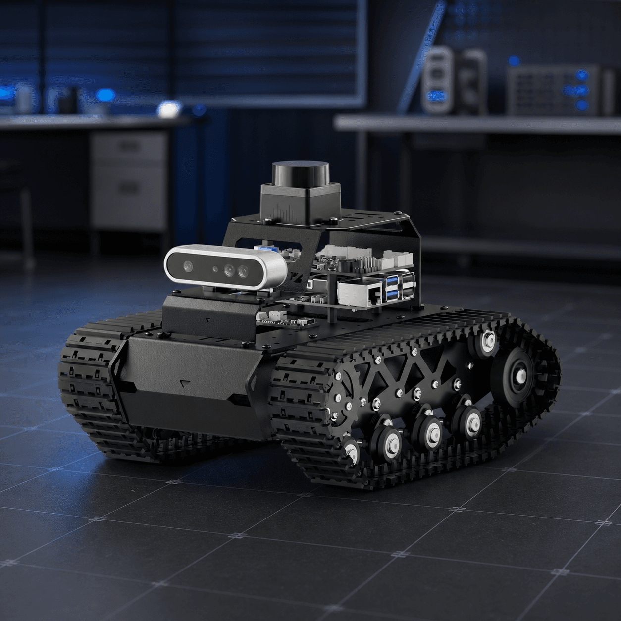
A practical reference architecture for an indoor teaching, prototype, or light-inspection robot: what to select, why the components fit together, how to integrate them, and which checks must pass before navigation is allowed to move the chassis.
The case: a useful first autonomous-mobile-robot milestone
This is a reference selection case for an indoor robot that needs to build a repeatable map, localize within it, and navigate at conservative speed in a known environment. It suits teaching, early R&D, demonstrations, and light patrol prototypes; it is not a claim that every room, obstacle, or operating condition is safe for autonomous motion.
The desired first result is deliberately modest: a stable robot can produce raw sensor data, move under supervised low-speed control, create a map, and repeat a short route. Selecting for that chain is more valuable than selecting the component with the longest headline specification.
Start with the operating constraints, not the LiDAR model
Write five constraints before choosing hardware: floor type and thresholds, the width of the narrowest passage, expected obstacle materials and heights, the required operating time, and whether the robot needs only planar navigation or also needs to understand objects above and below its laser plane.
For this case, the environment is a reasonably structured indoor floor with a clear, serviceable route for cables and a supervised test area. The robot must stop safely when a test fails. Transparent panels, mirrors, dark textiles, low floor objects, stairs, and changing public spaces are treated as separate validation risks rather than being assumed to be solved by a specification sheet.
Why a 2D dToF scanner is the right first navigation sensor here
HW-MS200-LIDAR supplies a rotating 360-degree horizontal scan for the navigation layer. Its published 0.03–12.0 m range is stated for a 90% reflective target, so it is useful for planning the test envelope but must not be read as a universal detection guarantee. The meaningful output is a time-stamped scan of distance, angle, and intensity that the robot can inspect before it makes motion decisions.
A single-line scanner works well when the navigation problem is mostly defined by walls, furniture, and legs that intersect its mounting plane. It is not a replacement for three-dimensional perception: low objects, glass, angled dark surfaces, and hazards outside the scan plane still require a physical test and, where needed, additional sensing or a more conservative operating boundary.
Reference component stack and each part’s job
HW-MENTORPI-T1-TRACK-BASE provides the tracked mechanical platform for the case. Start by validating the chassis as a motion and odometry system; do not regard a bare chassis listing as proof that every compute, sensor, battery, and accessory item is included. Confirm the final packing list for the selected configuration before purchasing.
HW-RPI5-8GB is the Linux and ROS 2 host for scan processing, mapping, navigation, networking, and application logic. HW-RRC-LITE sits between the host and the vehicle hardware, concentrating encoder-motor drive, IMU feedback, serial I/O, and the Raspberry Pi 5 power path in one control layer. This split keeps real-time vehicle connections explicit instead of hiding them behind ad-hoc wiring.
HW-MS200-LIDAR is the planar perception input. HW-7V4-2200-LIPO is the matching mobile battery configuration used in the reference platform. Treat these five items as the baseline discussion set; cooling, storage, charging equipment, cables, mounting hardware, and the exact delivered kit configuration still need to be checked separately.
Power and interfaces: the selection is only valid when the path is explicit
Draw the power path from battery to controller, the regulated 5 V path to the host and sensor, and every data path before ordering extra accessories. Confirm connector gender, polarity, voltage limits, current headroom, UART or USB availability, and cable strain relief against the delivered hardware—not against photos from a different configuration.
The RRC Lite reference controller is designed around encoder-motor and host integration, but that does not remove the need to measure voltage behavior. First verify the robot on a stand: the host should remain stable while motors start and stop, and the scan stream should not disappear when the drivetrain load changes. A capacity figure estimates runtime; voltage behavior under peak load determines whether the sensing and compute path remains trustworthy.
Mechanical placement and coordinate frames turn a scan into usable data
Mount the MS200 rigidly, level it, and keep its 360-degree scan plane clear of brackets, cables, and moving bodywork. Choose its height deliberately: an obstacle that does not intersect the laser plane cannot be expected to appear in the scan. Keep the mounting and cable route serviceable so that changes can be inspected after transport or maintenance.
Before mapping, document the base frame, LiDAR frame, wheel direction, encoder polarity, and IMU orientation. A clean scan with an incorrect transform can look convincing while producing a map that drifts or a planner that turns in the wrong direction. Coordinate-frame verification is therefore an acceptance step, not an implementation detail.
A five-gate validation sequence
Gate 1 — Power and raw data: with the robot stationary, confirm stable supply rails, a continuous LiDAR stream, and sensible readings against known static targets. Record the test conditions and retain a short raw-data capture for comparison after later changes.
Gate 2 — Motion and odometry: with wheels or tracks safely unloaded where appropriate, verify forward, reverse, left, and right commands, encoder direction, and IMU response. Repeat the test at low speed on the actual floor; do not move on to autonomy when manual motion is ambiguous.
Gate 3 — Geometry: inspect the scan frame in the robot model, then drive a short supervised loop and compare the estimated trajectory with the physical route. Resolve frame, wheel, or timing errors before creating a navigation map.
Gate 4 — Mapping and localization: make a small map in a controlled area, restart the navigation stack, and check whether the robot can localize consistently from a known start pose. A visually attractive map is not sufficient; repeatability matters more than one successful run.
Gate 5 — Supervised navigation: begin with an open route, a conservative speed limit, an accessible emergency stop, and a human observer. Add representative obstacles one category at a time. A failed detection or unstable pose estimate is a reason to narrow the operating boundary or add sensing, not a reason to raise the speed.
What success looks like in this case
The case is accepted when the team can reproduce the same hardware state, map a small indoor area, return to a known pose, and complete a short supervised route without losing power, odometry, or scan data. The output is a documented baseline: cable routing, frames, software versions, test map, power observations, and the conditions under which it was validated.
This is more useful than declaring the robot “autonomous.” It creates a decision record that another teammate can repeat, diagnose, and extend. It also makes it clear which risk belongs to hardware selection, which belongs to installation, and which belongs to software tuning.
When to add an RGB-D camera or change the architecture
Add HW-AURORA930-PRO when the task needs near-field three-dimensional information, such as detecting geometry outside the laser plane, visual recognition, reconstruction, or manipulation. Add it because the task requires another sensing modality, not because it is assumed to make every navigation failure disappear.
Choose a different base or sensing architecture when the route includes stairs, steep ramps, wet or outdoor terrain, safety-critical operation around people, or obstacle materials that fail the planar scan test. In those cases, revise the operating requirements first and then select the platform, safety layers, and validation plan to match them.
Procurement decision: buy the baseline, prove it, then expand
For a first build, purchase and verify the baseline motion, control, compute, planar sensing, and power path together. Do not defer cable, cooling, mounting, storage, or charging decisions until the system is already assembled; those details are part of the working robot.
Use this case as a selection checklist, not as a substitute for the delivered manual or a site-specific safety assessment. Confirm final specifications, included accessories, connector assignments, and software support for the exact order before commissioning the robot.
Ready to turn the method into specific parts?
Browse the parts catalogue