What this guide proves
HW-MS200-LIDAR provides a stable raw stream of distance, angle, intensity and timestamp data on the completed robot, with a measured frame orientation and an installation that does not obscure its horizontal scan plane.
Hardware and scope boundary
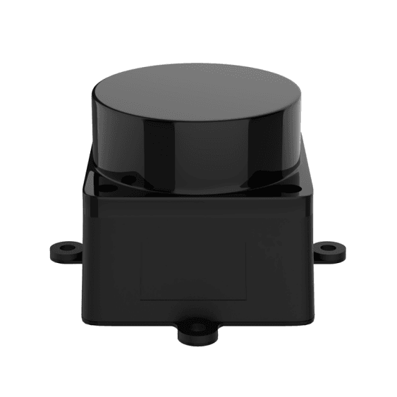
MS200 is a compact 40 g, 37.7 × 37.5 × 33 mm, single-line 360° dToF LiDAR. It expects 5.0 V ±0.5 V, uses a standard asynchronous UART and a compact 4-pin power/data connector. The published 0.03–12 m range is for a 90% reflective target; it is not a guarantee for dark, transparent, angled or out-of-plane obstacles.
Prepare before applying power
Use the exact delivered cable and pinout to identify 5 V, GND, TX and RX. Budget for the published startup and operating current, keep voltage ripple controlled, and mount the unit level with no bracket or wire passing through the scan plane.
Procedure
- Verify power and serial pins before mating the connector. Do not assume the connector matches a different LiDAR or use a USB adapter without confirming its UART implementation.
- Start the delivered or verified ROS/ROS 2 driver path on HW-RPI5-8GB and inspect raw scan output before launching a map or navigation node.
- At the default or documented scan setting, observe continuity, reported frequency and angular coverage while the sensor is stationary. Save a short raw-data sample.
- Place a known target at several conservative distances and inspect plausible distance/angle behavior. Test representative dark or reflective materials separately; do not extrapolate from a white wall.
- Measure the sensor frame relative to base_link, publish only that measured transform and perform a short supervised low-speed run to check for vibration, supply drop or cable stress.
Pass criteria and record
Keep the delivered pinout, driver/firmware identity, power observation, scan sample, target check, mounting photo and measured transform with the robot record.
Do not proceed when
Stop if pinout is guessed, data drops when the chassis moves, scan-plane obstruction is visible, target response is inconsistent, or a required obstacle falls outside the single horizontal measurement plane.
Continue from here
Use the MS200 as a planar input to LiDAR SLAM and Nav2 only after raw scan and TF acceptance are complete. Add another sensing modality when the task demands 3D coverage.